Home
Actuator Wiring Diagram . The function of a linear actuator is quite simple; The relay wiring will need to be routed along vehicle frame from the battery to the actuator on plow.
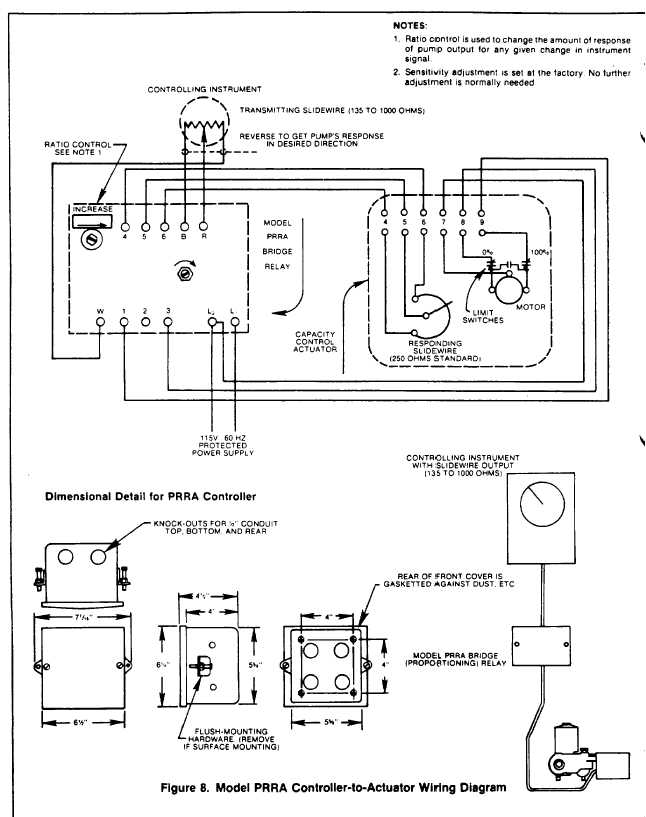
Figure 8 Model Prra Controller To Actuator Wiring Diagram from waterdecontamination.tpub.com Electric power to terminals 1 and 3 will cause the shaft to rotate clockwise. When the tabs are lowered, the water flow is redirected, creating an upward force at the stern of the boat. In canada, all wiring must be done in accordance with the canadian electrical code (csa c22.1). Page 4 english jandy® pro series valve actuator | installation and operation manual Both motor legs rest at ground at the relays.
The hitch ball and tow vehicle must be rated to handle the actual gross vehicle weight (gvw) of the trailer and load. The hitch ball and tow vehicle must be rated to handle the actual gross vehicle weight (gvw) of the trailer and load. Electric actuators offer a compact, efficient design with minimal environmental impact. For specials or if you can't find what you want, please contact rotork. The hitch ball and tow vehicle must be rated to handle the actual gross vehicle weight (gvw) of the trailer and load. It reveals the components of the circuit as streamlined shapes, as well as the power and also signal links in between the devices. It moves an object in a linear motion.
Source: www.researchgate.net Electric actuators offer a compact, efficient design with minimal environmental impact. Wire gauge selection dc actuators long lead wires between the power source and the actuator will result in a voltage drop for dc units. Since lenco actuators are electromechanical, they provide an immediate response at the touch of the switch.
As far as indicator for 2/4wd i wired mine up to lights since i went prerunner to 4wd. Connect power to the terminal block according to the schematic wiring diagram inside the actuator cover. Wiring diagram codes for iq3/iqt3 range.
Is noted on the actuator name tag and wiring diagram. As far as indicator for 2/4wd i wired mine up to lights since i went prerunner to 4wd. Dresser rcs actuator wiring diagram.
Source: images.squarespace-cdn.com I have also attached a short video review that you can check out. I chose this wire based on the wiring diagram, which showed fuse 24 in the ip fuse box feeding voltage to the front axle motor. The hitch ball and tow vehicle must be rated to handle the actual gross vehicle weight (gvw) of the trailer and load.
Connect terminal n01 to white wire from actuator to drive the valve stem to the rotation switch position. Depending on how the unit is wired, one can control it in many different ways. A wiring diagram usually gives information very nearly the.
Wire type and wire installation tips Drawings/dimension data standard a drawings: It moves an object in a linear motion.
Source: www.manualsdir.com It reveals the components of the circuit as streamlined shapes, as well as the power and also signal links in between the devices. The function of a linear actuator is quite simple; The transformers are properly sized.
Since lenco actuators are electromechanical, they provide an immediate response at the touch of the switch. The transformers are properly sized. A wiring diagram usually offers details concerning the loved one.
Multiple actuators positioned by the same control signal may be powered from multiple transformers provided the following rules are followed: Is noted on the actuator name tag and wiring diagram. When the tabs are lowered, the water flow is redirected, creating an upward force at the stern of the boat.
Source: www.haitima.com.tw Ensure that the terminate field wiring per the appropriate rcs wiring diagram supplied 2 | dresser. Page 4 english jandy® pro series valve actuator | installation and operation manual Albanian arabic azerbaijani bulgarian chinese croatian czech danish dutch english english (usa) estonian finnish french german greek hungarian icelandic italian japanese kazakh korean latvian lithuanian macedonian norwegian persian polish.
Forum's abz™ product line includes. As far as indicator for 2/4wd i wired mine up to lights since i went prerunner to 4wd. Please contact our documentation department documents@auma.com.
Connect terminal n01 to white wire from actuator to drive the valve stem to the rotation switch position. Connect terminal ac to red wire from actuator to provide power. Is noted on the actuator name tag and wiring diagram.
Source: cdn.shopify.com The relay wiring will need to be routed along vehicle frame from the battery to the actuator on plow. When the stern rises, the bow will lower. As far as indicator for 2/4wd i wired mine up to lights since i went prerunner to 4wd.
Lower left is 2wd indicator, lower middle is 4wd indicator, lower right is ground for the indicator pins. The wiring diagram selector returns standard iq3/iqt3 range wiring diagrams only. The wiring diagram service provides the wiring diagrams for our products according to:
Top two are for the motor, you switch polarity to spin motor forward and backwards using a dpdt switch. 1 wires from all actuators are tied together and tied to the negative leg of the control signal. Ensure that the terminate field wiring per the appropriate rcs wiring diagram supplied 2 | dresser.
Source: covnaactuator.com Electric actuators offer a compact, efficient design with minimal environmental impact. The wiring diagram selector returns standard iq3/iqt3 range wiring diagrams only. For a complete wiring diagram, refer to the wiring information.
The hitch ball and tow vehicle must be rated to handle the actual gross vehicle weight (gvw) of the trailer and load. Electric power to terminals 1 and 2 will cause the shaft to rotate counterclockwise. To the coil of the respective relay.
The hitch ball and tow vehicle must be rated to handle the actual gross vehicle weight (gvw) of the trailer and load. If not, the arrangement will not work as it should be. Depending on how the unit is wired, one can control it in many different ways.
Thank you for reading about Actuator Wiring Diagram , I hope this article is useful. For more useful information visit https://thesparklingreviews.com/