Home
3 Pin Dmx Wiring Diagram . The last dmx device on the line must be terminated with a termination switch or resistor with a value of 100 to 120 ohms between pins 2 and 3. (the rear view is the end you solder from) here are the connections on each pin:
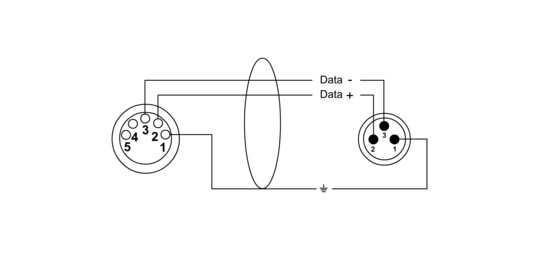
Cpd Fm 5 3 from www.cordial-cables.com 5 pin xlr connector wiring diagram connecting a microphone. I admire the valuable information and facts you offer. Wire must be belden 9829, 9842, cat 5 or equivalent. 5 prong wiring diagram wiring diagrams folder. Dmx/rdm is a robust and reliable system for lighting control.
The board status led should be flashing fast green. (the rear view is the end you solder from) here are the connections on each pin: The xlr's pins are labeled in the plastic on the front. Use the appropriate wire for all connections. Such equipment is not compliant with the dmx standard, but may be sufficiently compatible for operation using simple adapters. I admire the valuable information and facts you offer. • wiring must be run separately from line / mains voltage.
Source: www.doityourselfchristmas.com Connect the xlr pin 1 on the male to the female. The last dmx device on the line must be terminated with a termination switch or resistor with a value of 100 to 120 ohms between pins 2 and 3. However, if not implemented correctly, problems can arise such as random flashing of lights, erratic operation and delays in responding to commands.
(the rear view is the end you solder from) here are the connections on each pin: Dmx cables are most commonly made with 2 core shielded data cable terminated at either end with 3 or 5 pin xlr connectors (one male, one female). Dmx data+, because that is the standard.
The dmx data itself requires only 2 of the cable cores plus the shield so recent devices have moved to the 3 pin format. Measure out how much wire you will need, try to use as little as possible to reduce interference. Dmx wiring guide created date:
Source: dmx-wiring-color-code.istent470s.pw Dmx/rdm is a robust and reliable system for lighting control. Wiring diagram dmx wall controller dmx wall controller power supply led strip rgb | rgb/w strip led strip rgb | rgb/w strip led strip rgb | rgb/w strip dmx decoder dmx decoder keep it up! Cat5 or equivalent is not preferred as a portable cable since it is not as rugged as other dmx cables.
Dmx (digital multiplex) is a communications protocol used mainly to control stage lighting. Dmx wiring guide created date: 3 pin xlr connectors are standard amongst line level and mic level audio applications.
The last dmx device on the line must be terminated with a termination switch or resistor with a value of 100 to 120 ohms between pins 2 and 3. I admire the valuable information and facts you offer. What are the standard dmx 512 pinouts interactive.
Source: i.pinimg.com • total length of control link must not exceed 2000 ft (610 m). Dmx cables are most commonly made with 2 core shielded data cable terminated at either end with 3 or 5 pin xlr connectors (one male, one female). 6 pin dmx wiring diagram 7 pronge trailer connector diagram.
Xlr connectors are used extensively in both audio and lighting. Cat5 or equivalent is not preferred as a portable cable since it is not as rugged as other dmx cables. Traditionally, 3 pin connectors have been the domain of audio and 5 pin xlr connectors have been the domain of dmx control for lighting.
Dmx (digital multiplex) is a communications protocol used mainly to control stage lighting. This pinout is the same for both the male and female sides of the cable and yes the sheild is required to be soldered the only pins that are optional are pins 4 and 5. 5 prong wiring diagram wiring diagrams folder.
Source: lh5.googleusercontent.com The last dmx device on the line must be terminated with a termination switch or resistor with a value of 100 to 120 ohms between pins 2 and 3. +12v, because lor also uses this pin for power. Cat 5 wiring diagram dmx wiring diagram, all submitted content remains copyrighted to its original copyright holder.
Connect the xlr pin 2 on the male to the female. The last dmx device on the line must be terminated with a termination switch or resistor with a value of 100 to 120 ohms between pins 2 and 3. Dmx data+, because that is the standard.
Wire must be belden 9829, 9842, cat 5 or equivalent. Cat5 utp cable may be used inside metal conduit. The board status led should be flashing fast green.
Source: qph.fs.quoracdn.net Dmx cables are most commonly made with 2 core shielded data cable terminated at either end with 3 or 5 pin xlr connectors (one male, one female). Cat5 utp cable may be used inside metal conduit. Traditionally, 3 pin connectors have been the domain of audio and 5 pin xlr connectors have been the domain of dmx control for lighting.
(the rear view is the end you solder from) here are the connections on each pin: You can't use 3 and 5 pin dmx jacks on fixtures as a split! Cat5 or equivalent is not preferred as a portable cable since it is not as rugged as other dmx cables.
The xlr's pins are labeled in the plastic on the front. Dmx decoder dmx decoder power supply power supply power supply. Rj45 connectors may be used with cat5 cable, for permanent wiring.
Source: s1.manualzz.com +12v, because it was what was left over (see below). • total length of control link must not exceed 2000 ft (610 m). Measure out how much wire you will need, try to use as little as possible to reduce interference.
Xlr connectors are used extensively in both audio and lighting. +12v, because lor also uses this pin for power. This terminates the incoming dmx input with a 120 ohm resistor.
Dmx (digital multiplex) is a communications protocol used mainly to control stage lighting. • wiring must be run separately from line / mains voltage. How to choose the right speaker wire/cable?
Thank you for reading about 3 Pin Dmx Wiring Diagram , I hope this article is useful. For more useful information visit https://thesparklingreviews.com/